A pipe flange connects piping and components in a piping system by use of bolted connections and gaskets. Most commonly used flanges are weld neck flange, slip on flange, blind flange, socket weld flange, threaded flange and lap joint flange (RTJ Flange). This type of connection in a pipe flange allows for ease of disassembly and separation for repair and regular maintenance. Most common specification for carbon steel and stainless steel flange is ANSI B16.5 / ASME B16.5.
Metal flanges are commonly used for industrial, commercial, and institutional application. Steel pipe flanges are available in variety of styles and pressure classes. Metal flanges are classified from 150 to 2500 # rating. In addition to specifying pressure class, certain flanges such as weld neck flange & socket weld flange also require specifying the pipe schedule. This ensures the pipe bore will match the bore of the weld neck or socket weld flange.
Trupply offers wide variety of pipe flanges in carbon steel, stainless steel and nickel alloy. We can also provide special flanges such as long weld neck flange, special material request and high-yield pipe flanges.
As common as it may seem to many people, a lot of customer ask what is a flange? Trupply has created a demonstration video to explain different types of flanges, its features and how they are used on the pipe. Metal flanges are manufactured as per ASME B16.5. These flanges are also called ANSI Flanges.
There are six most commonly used flanges, also knows as ANSI Flange, ASME B16.5 Flange.
Weld Neck Flange

|
|
This flange type is designed to be connected by a butt weld connection to the pipe or equipment requiring a flanged joint. Welding neck provides good service under variety of temperature and pressure applications. A weld neck flange must specifiy the pipe schedule for the bore. Due to the welding neck, it is a popular choice on pressure vessels and for creating man-holes etc. These flanges are also knows as ANSI Flange or ASME B16.5 Flange

|
|
A slip on flange is designed to slip over the end of pipe. It allows for easy positioning before welding. Both the inside and outside of the pipe is welded on the slip on flange. See picture on the right. The pipe is generally inserted all the way, inside the slip on flange, leaving only the gap equivalent to wall thickness of pipe. These flanges are also knows as ANSI Flange or ASME B16.5 Flange

|
|
A lap joint flange is also knows as Van Stone Flange. This type of flange consists of both a stub end and a flange.The flange itself is not welded but rather the stub end is inserted / slips over the flange and is welded to pipe. This arrangement helps in flange alignment in conditions where non-alignment may be an issue. In a lap joint flange, the flange itself is not in contact with the fluid. The stub end is the piece which gets welded to the pipe and is in contact with the fluid. Stub ends comes in type A and type B. Type A stub ends are most common. Lap joint flange only comes in flat face. People confuse lap joint flange with slip on flange as they look very similar with the exception that lap joint flange has round eges on the back side and a flat face.

|
|
Threaded flange is also called screwed flange or screwed-on flange. This type of flange is used where welding is not an option. Threaded flange is most commonly used on low pressure applications and smaller pipes (up to 4" nominal).

|
|
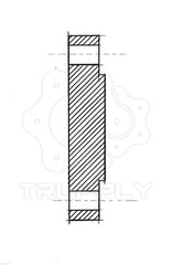
A blind flange is a solid flange with no bore or threaded hole and is used to close the end of pipe, fittings, valves or equipment. Blind pipe flange is also used for pressure testing equipment. Blind flange comes both as raised face and flat face.

Spectacle and line blind flanges are similar to a blind flange but different because they fit between two flanges. Spectacle blind gets their name from similarity to pair or eye glasses. Once side of spectacle blind is fully closed for complete flow shut off, whereas the other end is open for full flow. In this setup the blinds can be rotated without having to take the system apart. It also gives visual confirmation if the line is open or close.

Orifice flange is a special flange and is always used in pairs. It is used in conjunction with orifice plate for measure flow of liquids and gases in a piping system. Orifice flanges are pre-drilled with tapped holes made in the flange rims to accommodate metering pipe. The flange that makes up the orifice flange is usually a welding neck flange. Slip on and threaded flange are also used sometimes as end connection. In an orifice flange, the pipe must be drilled to accommodate the tapped hole through which the pressure is sensed. The picture above illustrates the working of orifice flange in a welding neck flange arrangement.

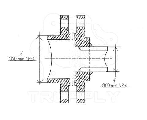
A reducing flange changes the line size without adding an extra fitting. The reduction in a reducing flange is always abrupt compared to a reduction that can be achieved by concentric butt weld reducer. A reducing flange is commonly available as threaded reducing flange or slip on reducing flange. A 6" by 4" reducing slip on flange will have the flange dimension (outer diameter, bolt circle diameter) of an 6" flange but the hole of a 4" flange. This allows it to mate to an 6" pipe via flanged connection but connect a 4" pipe instead.
Flange face provides a mean to mate the flange with sealing element, usually a gasket. Even though there are many face types, most common flange face types are following;
There are two type of flange face finishes for Raised Face and Flat Face Flanges;
Both serrated finishes have grooves 1/16" deep with 24 to 60 groves per inch.

Flange markings are governed by ANSI ASME codes. Flange marking includes;

|

|
Description
This standard cover forged carbon steel piping components for ambient- and higher-temperature service in pressure systems. Flanges are ordered either to dimensions specified by the purchaser or to dimensional specifications such as ASME 16.5 and API 6A. Forgings made to ASTM A105 are normally limited to maximum weight of 10,000 lbs. .
Specifications
ASTM: A105
ASME: SA105, B16.5
NACE: MRO175
MSS: SP 44
Chemical Composition%
|
C |
Mn |
P |
S |
Si |
Cu |
Ni |
Cr |
Mo |
V |
|
0.35 |
0.60-1.05 |
0.035 |
0.04 |
0.10-0.35 |
0.4 |
0.4 |
0.3 |
0.12 |
0.08 |
|
max |
– |
max |
max |
– |
max (1) |
max (1) |
max (1-2) |
max (1-2) |
max |
Note: For each reduction of 0.01% below the specified carbon maximum (0.35%), an increase of 0.06% Manganese above the specified maximum (1.05%) will be permitted up to a maximum of 1.35%.
Tensile Requirements
Tensile Strength: (KSI) = 70
Yield Strength: (KSI) = 36
(KSI converts to MPA {Megapascals} by multiplying by 6.895)
Typical Application
Description
Type 316 is a molybdenum steel processing improved resistance to pitting by solutions containing chlorides and other halides. In addition, it provide excellent tensile, creep and stress-rupture strengths at elevated temperatures. Type 316 is available in low carbon (316L) and high carbon (316H) alloys.
Specifications
ASTM: A312, A376, A358, A269, A249, A403, A182, A351, A479, A276
ASME: SA312, SA376, SA358, SA269, SA249, SA182, SA276, SA403, SA479, SA351
Chemical Composition%
|
C |
Cr |
Mn |
Mo |
Ni |
P |
S |
Si |
|
MAX |
– |
MAX |
– |
Max |
MAX |
MAX |
|
|
0.035 |
16.0- 18.0 |
2.00 |
2.0-3.0 |
10.0-14.0 |
0.045 |
0.030 |
1.00 |
Tensile Requirements
Tensile Strength: (KSI) = 70
Yield Strength: (KSI) = 25
(KSI converts to MPA {Megapascals} by multiplying by 6.895)
Typical Application
Description
304 stainless is a low-carbon (0.08% max) version of the basic 18-8, also known as 302. Type 302 has 18% chromium and 8% nickel. Type 304 has a slightly lower strength than 302 due to its lower carbon content. Type 304 is used in welding applications, because the low carbon permits some exposure in the carbide precipitation range of 800° F -1500° F without the need for post-annealing operations. However the severity of the corrosive environments may necessitate annealing after welding or the use of 304L. Type 304L has a carbon content of 0.03% or less.
Specifications
ASTM: A312, A376, A358, A269, A249, A403, A182, A351
ASME: SA312, SA376, SA358, SA269, SA249, SA403, SA182, SA351
Chemical Composition%
|
C |
Cr |
Mn |
Ni |
P |
S |
Si |
|
MAX |
– |
MAX |
– |
MAX |
MAX |
MAX |
|
0.035 |
18.0- 20.0 |
2.00 |
8.0-13.0 |
0.045 |
0.030 |
1.00 |
Tensile Requirements
Tensile Strength: (KSI) = 70
Yield Strength: (KSI) = 25
(KSI converts to MPA {Megapascals} by multiplying by 6.895)
Typical Application
Author:
Ms. Sunny Peng
Phone/WhatsApp:
+8618333120628
September 13, 2022
September 13, 2022
September 09, 2022
September 09, 2022
May 26, 2021
이 업체에게 이메일로 보내기
Author:
Ms. Sunny Peng
Phone/WhatsApp:
+8618333120628
September 13, 2022
September 13, 2022
September 09, 2022
September 09, 2022
May 26, 2021